Basic Design
The basic blade shape is shown here. Please refer to ‘How to build a wind
turbine: the axial flux windmill plans’ for full details of the shape, curve and
size of the blade. This is the 6 foot (1kW) version of the wind turbine design.
Please note the definitions for Tip, Root, Leading edge, Trailing edge,
Stringer, Wooden core, Windward side, Backward side as these will be used
throughout this text.
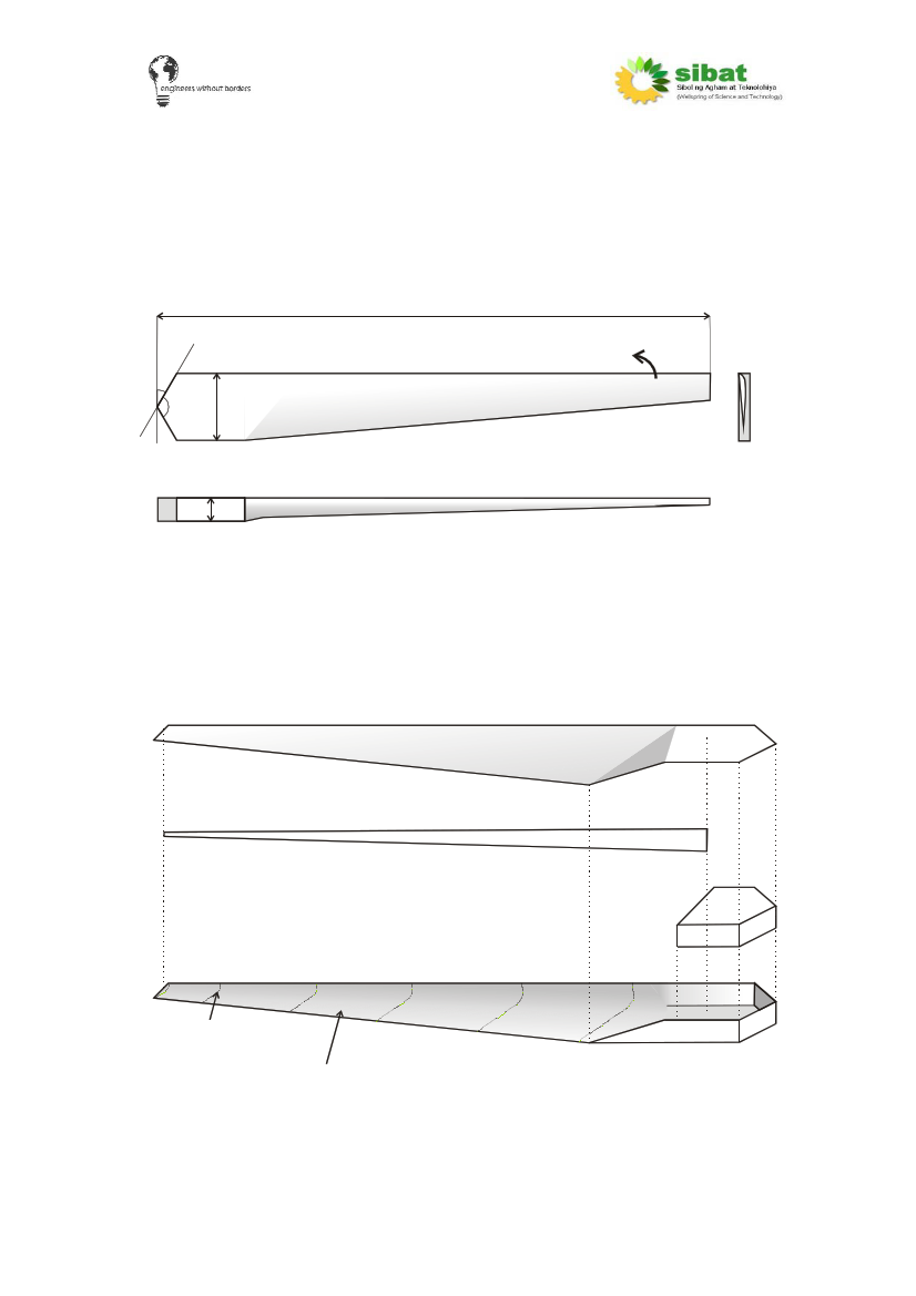
View from front
30º (which faces the wind)
1.8m (6’)
Leading edge
Drawing not to scale
Blade rotational
direction
120º 20cm (8”)
Root
View from side
Trailing edge
Tip
View from tip end
5cm (2”)
The blade is comprised of two main halves (both made from fibre glass), a
wooden core at the root and a ‘stringer’ along the inside from root to tip. Once
the blade has been constructed and stuck together, a two-part expanding
foam is used to fill the structure of the blade helping to add strength and
rigidity to the blades.
“Exploded” view of blade construction
Windward side
Stringer
Wooden
core
These lines are just
to show curve of blade
Backward side
The space within the blade is filled with
two part expanding foam
5